
|
|
|
 04-13-09, 01:08 PM
|
#1 |
|
Supreme EcoRenovator

Join Date: Mar 2009
Location: Portland, OR
Posts: 4,004
Thanks: 303
Thanked 723 Times in 534 Posts
|
Most of the sources I respect advise doing a heat transfer test to determine the rate at which heat will be transferred into the earth (for cooling) or out of the earth (for heating). This transfer rate will be the same in each direction, and will determine how much loop-field (trench or borehole) will be required to heat or cool your house. This is important because the loopfield is the most expensive part of the GSHP installation process if you are hiring it out, and is a lot of work if you are doing it yourself. So it's a good idea to get it right. Too little loop-field won't be able to supply the heating or cooling required. Too much, while not such a bad idea, means greater expense and greater work.
So I went on a google-frenzy to try to locate testing and evaluating proceedures, and after many, many hours, finally turned this up: http://www.geokiss.com/tech-notes/TCTestingSum.pdf So, I consider this test to be my first attempt at testing and likely to be a candidate for improvement, but this is what I did... I had used a hand auger, meant for fence posts, and had dug to a depth of twelve feet in about 3 or 4 hours. I was going to fill the hole back in, but I decided to try to get some use out of the hole along the way. I buried a double loop of CPVC pipe I had laying about in the garage and attached some garden hose to the input an output of the loop. (see photo) Then I filled the hole back up with the dirt that I had laboriously augered out and used water on the dirt as I went, so it would settle well. I hadn't actually found the testing method document that I'm linking to above at the time I started testing, so I was just sort of making it up as I went along. I reasoned that if I introduced a known amount of heat-energy into the CPVC-loop, the ground would absorb the heat-energy at a rate that I suspected would decline. I further reasoned that if I monitored the temperature of the water, it would tell me something about the rate of absorption of heat by the ground. If the ground absorbed the heat at a high rate, the water temperature would be low, if it absorbed the heat energy at a lower rate, the water temperature would be higher. So here's a sketch of my setup and a few photos: 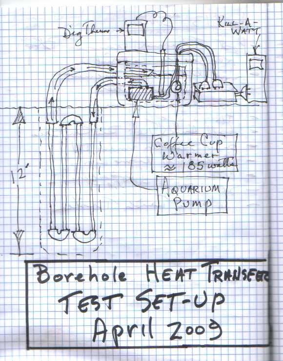  this shows the hole I'm doing the tests in. I used CPCV pipe (not recommended) with a double-loop (not much advantage over a single loop)... 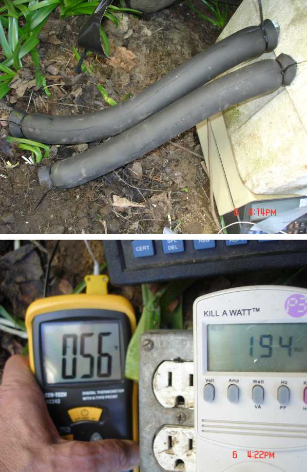 I thought it would help to eliminate error if I used good pipe insulation on the hose. Bottom photo shows digital thermometer and kill-a-watt. A good analog thermometer would work just fine, but the digital is much easier to use. The kill-a-watt meter has a 'watt' function. It was set up to measure both the pump & the heater together, since they both give off heat. I found that the watts vary over time, so they need to be recorded at every chosen interval. It also has an elapsed-time function (called 'clock'), very handy.  this shows the set-up in the cooler box. I initially thought that it would be a good idea to put the coffee cup warmer inside of something so it wouldn't melt the foam box. I nixed this idea, and suspended the heater from the hose with a bread wrapper twist-tie. If you read the proceedure I am using for my guide, you'll notice that the proceedure call for measuring the input and the output temperatures from the ground loop that is under test and arithmetically averaging them. I made the simplifying assumption that the water swirling around in the cooler box would physically average the temperature. (NEXT POST: thermal transfer test data & analysis) >>>>>>>>>>>>>>>>>>>>>>>>>>>>>>>>>>>>>>>>>>>>>>>> > Last edited by AC_Hacker; 05-27-09 at 02:07 PM.. Reason: in-line images... |

|

|
|
04-13-09, 11:33 PM
|
#2 |
|
Supreme EcoRenovator
Join Date: Mar 2009
Location: Portland, OR
Posts: 4,004
Thanks: 303
Thanked 723 Times in 534 Posts
|
So here's my test data & analysis...
Time Temp ____________ 0.00<tab>54 0.133<tab>57 0.167<tab>57 0.50<tab>60 1.733<tab>70 4.00<tab>79 6.25<tab>83 7.50<tab>85 8.433<tab>86.5 14.833<tab>92 15.25<tab>92 15.517<tab>92.5 19.883<tab>96 21.00<tab>96 22.083<tab>97 24.03<tab>100 25.82<tab>100 27.65<tab>99 31.67<tab>99 40.317<tab>99 44.23<tab>101 49.60<tab>102 63.65<tab>102 68.93<tab>103 89.55<tab>106 102<tab>107 113<tab>107 123<tab>108 143<tab>109 (I had to use the "<tab>" thingies, because the real tab didn't appear correctly in this blog) Since I don't have an automatic data logger (yet) I logged all the data by hand. The time intervals were irregular but I think that it doesn't matter so much. The first thing I did was to put the data into a curve analysis program. The program I found is a really great shareware program called CurveExpert for Windows available here: CurveExpert 1.3: Download I've used this program for lots of things. There are even tutorial pages available, if you need. At any rate, it was very useful to get well done graphs as the test progressed. The program does automatic curve fits and it was interesting to see that the program selected various curves before finally settling on an MMF type curve. heat transfer curve From CurveFit, it's even possible to get the equation of the curve that is the best fit and to project the curve forward in time. I was interesting to predict what the temperature would be at a particular time and to check the results as they came in. But this wasn't really getting me what I needed, which was a quantified characteristic of the earth formation in my yard. This is where the document mentioned in the previous post: TCTestingSum.pdf, came to the rescue. I tried to follow the proceedure but wasn't able to get the same results as the author had. Either I was making a mistake, or I was using a version of Excel that was older and didn't have the exact feature he was using. But I devised a work-around and got reasonable results. Here was my proceedure: 1) Start Excel 2) Open the data from a tab-delimited text file. This just means that the data is written in a test file and you hit the 'tab' key after the Time data, but before the Temp data. If the tab could print like this: <tab>, your data would look like this: ... 0.00<tab>54 0.133<tab>57 0.167<tab>57 ... Anyway this is a standard text format that Excel understands. ...of course you could just enter the data straight away into Excel and I could save myself some time & typing. If you graph the data I have included, it would look like this: See picture Looks similar to the graph from CurveExpert. At this point, the author of TCTestingSum.pdf was able to do a right-click on the graph curve that Excel made. Then he was able to choose "Add Trendline" and then a Logarythmic trendline, and the result, as illustrated, was a linear graph. I was not able to get these results, certainly not the graph as illustrated. So my modification to the process was to return to the spreadsheet, 'Insert' a column between the Time data and the Temp data. Then I wrote a simple formula (=ln(A1)) that took the natural log of the data in the time cell. I copied this formula down to the rest of the data cells. Then I made another graph of these data columns, "ln(Time)" and "Temp". At this point, I got a graph that resembled the illustrated results.  line slope graph I then did the right-click and 'add trendline' this time I chose "Linear", since the natural log function had essentially linearized the graph. This did give me a formula with slope. Then I was able to use the rest of the proceedure as described. This all gave me a "k" value of 0.569464441. I was in turn able to use this value to calculate the total length of borehole, which would yield 12,000 BTU/hr. This calculated borehole length came to 214.23 feet. Which is reasonable, as I hear from local installers that they estimate that 12,000 BTU/hr (AKA: one Ton) borehole length to be in the range of 175 to 225 feet. I have attached my spreadsheet for your consideration. Some improvements: * Get a real data logger * Use the actual type and configuration of Polyethylene pipe I plan to use in the actual installation. * Use a borehole that is closer to the actual location of the installation (the test borehole was within three feet of my basement, so error is to be expected) * use the type of grout I plan to use. I'm currently planning to use "mix-111", more information available here: Information Bridge: DOE Scientific and Technical Information - Sponsored by OSTI I welcome your comments. Best Regards, -AC_Hacker P.S.: For those who want to know more about the topic of borehole testing, I have located what might be the definitive paper on the subject: http://epubl.luth.se/1402-1544/2002/...DT-0239-SE.pdf P.P.S.: Here is a link to a report from a professionally done borehole test. Note the unusually high results and the speculation as to why such unusual results were obtained.: http://www.tva.gov/commercial/TCStud...iles/Se-02.pdf ...and another done in Alabama in 2000. These are more typical results. http://www.tva.gov/commercial/TCStud...iles/Jo-18.pdf ...and yet another done in Illinois in 2008. http://www.midwestsustainable.com/Co...%20Example.pdf >>>>>>>>>>>>>>>>>>>>> Last edited by AC_Hacker; 05-27-09 at 02:14 PM.. Reason: Links to misc. borehole tests |
|
|
|
|
01-02-12, 02:31 AM
|
#3 | |
|
Lurking Renovator
Join Date: Jan 2012
Location: NE Portland, Oregon
Posts: 3
Thanks: 0
Thanked 1 Time in 1 Post
|
ahhh ****.. that's so cool that you tested the conductance of your soil... I got some temporary data loggers that you can borrow if you need to do some more analysis...
I would have probably used an ice bath though in order to better simulate the conditions; that is, cold HX fluid... warm earth.. It would have also been interesting to test how quickly the earth temperature recovers during and after a 'long' run-time... and tested that against the theoretical recover times.. I believe the 'lumped capacitance' method is used... I recommend "The Fundamentals of Heat and Mass Transfer" by Incropera/Dewitt.. and I got a copy if you want to borrow it... the formulas are actually pretty easy to do... Quote:
|
|
|
|
|
|
04-13-09, 11:16 AM
|
#4 |
|
Supreme EcoRenovator
Join Date: Mar 2009
Location: Portland, OR
Posts: 4,004
Thanks: 303
Thanked 723 Times in 534 Posts
|
metroschultz,
I'm not sure where you live, but here in Portland, Oregon the city is being extremely slow to make progress on greywater. In the meantime, quite a few citizens have taken charge of their own lives and are quietly and safely operating greywater systems. -AC_Hacker |
|
|
|
|
04-13-09, 12:12 PM
|
#5 |
|
nail bender

Join Date: Sep 2008
Posts: 9
Thanks: 0
Thanked 0 Times in 0 Posts
 |
I have considered that.
Too afraid of big brother  . .
__________________
Electricity is really just organized lightning. To view links or images in signatures your post count must be 0 or greater. You currently have 0 posts. |
|
|
|
|
04-15-09, 08:26 PM
|
#6 |
|
Apprentice EcoRenovator

Join Date: Dec 2008
Location: mid michigan
Posts: 191
Thanks: 0
Thanked 0 Times in 0 Posts
|
I am very interested in your thread. Nice work so far too
 . You shop at Goodwill too, one of my favorite places to check , right up there with garage sales! . You shop at Goodwill too, one of my favorite places to check , right up there with garage sales!I have been wanting to mess around with heat pumps. I can get ahold of old ac units and dehumidifiers but have been afraid to mess with the original plumbing. It's just something I haven't had much hands-on experience with. What did you have to do to the Ac unit you converted in the picture you posted in the beginning of the thread? |
|
|
|
|
04-16-09, 02:50 AM
|
#7 |
|
Supreme EcoRenovator
Join Date: Mar 2009
Location: Portland, OR
Posts: 4,004
Thanks: 303
Thanked 723 Times in 534 Posts
|
jwxr7,
First the disclaimer: I am not an HVAC technician. In fact, I am barely a hacker. Some of the things I describe may be against the law in the country or state in which you live. I do not encourage anyone to do anything that is unlawful. Additionally some HVAC equipment contains gases that are known to cause lasting damage to the atmosphere and also to cause global warming, so the manufacture of these gasses, the utilization of these gasses and the venting of these gasses into the atmosphere is also unethical and immoral. As if that were not enough, working with HVAC gasses in an enclosed space can be very dangerous because they have little or no odor and while they are not leathal of themselves, they can displace oxygen in the lungs, causing you to pass out and possibly die. Also, refrigerant gasses are under very high pressure, when they rapidly expand, can instantly cause frostbite of the fingers, and if they sprayed in your face, could cause loss of eye-sight. So, be warned, be very careful, do not work in a confined space, do not work without eye protection, do not work alone. This is serious stuff. You should familiarize yourself with proper and legal methods of handling refrigerant gasses. Act as if your life and physical intregity depend on what you do. Because my friend, it is true. Now if you read all of the above, you should have a bit of respect for the process. Having said all that, I have learned most everything I know about creatively re-purposing HVAC equipment, from German children. That's right I said German children. There are some fantastic blogs out there where German children describe in precise detail how they were able to take old air-conditioners and re-configure them and re-charge them with propane (aka: r-290; Barbeque Gas, etc), all so that they could super-cool the CPUs on their video games and play video games faster. I stand in awe of German children. I would urge you to go on a Google-frenzy and search out what these kids have done. Here are a few suggested terms: * Extreme Systems * Vapor Phase Change Cooling * the term "German Children" will not be very useful ...be creative... You're also gonna need some tools: * Copper tubing cutter (cheap) * A Manifold Gauge Set ($5 to $100) * A good brazing tourch. I suggest Mapps gas, it's hotter ($35) * Brazing rod with silver content from 10% to 40%. No, solder or silver solder is not good enough because refrigeration systems vibrate and solder does not have the physical strength. I've even heard HVAC folks use the term "solder" (like "...solder it back up."), but on inquiry, found out that they were actually referring to brazing. * A good vacuum pump with fresh vacuum pump oil every time you use it. I got my vacuum pump for free, a friend of mine bought it off ebay, the rotor was stuck so he just gave it to me. I freed up the rotor, put fresh oil in it, let it run for about 8 hours and tested it and saw that it would pull down to about 80 microns. * When you're serious, a micron vacuum gauge (ultra low pressures). I built my first system without a micron gauge, but I was never quite sure if I really got the vacuum low enough, or if my equipment which was all second hand was really any good. If you can borrow a micron gauge to test your equipment, that would be a big help. ...ebay and garage sales and pawn shops are good places to start looking. Some things to keep in mind: * go for Air-Conditioners or de-humidifiers, they're more robust than refrig compressors * Make sure you start with a working unit. Try it out. Make sure it runs & gets cold. * A neighborhood AC shop could extract the refrigerant for a modest cost, when you're ready to go, they might even do the recharge, if they like you and are interested in what you're doing. I have heard that it is even possible to use a spare refrig compressor for an extractor, but I have no first hand knowledge of this. * don't 'open' the system until you are actually ready to convert it to your purposes. Refrigeration systems last a long time if their internal atmosphere is just gas & oil and NO WATER. Refrigeration oil loves watrer and will absorb and hold moisture in the air. So when you open the system the clock is ticking. Try to get it together, brazed, tested, vacuumed and re-charged ASAP. * In my experience, a lot of the people who are in the HVAC trade are not so very happy to see new people experimenting with refrigeration. They may be blunt, maybe discouraging, might even threaten to turn you in to the HVAC police. But, if you find someone in the HVAC trade who is heplful, treat them with all the respect you can muster, they're your lifeline. * I have noticed that there are loads of HVAC manuals, etc. floating about in the Peer-to-Peer world. If torrents won't locate anything useful, eMule just might. Here is a link to a Danfoss manual on the basics of refrigeration, good information. (NEXT POST: Selecting a likely candidate for building a heat pump.) Last edited by AC_Hacker; 01-07-11 at 03:28 AM.. |
|
|
|
| The Following User Says Thank You to AC_Hacker For This Useful Post: | castlusion (03-02-13) |
|
04-16-09, 07:51 AM
|
#8 |
|
Apprentice EcoRenovator
Join Date: Dec 2008
Location: mid michigan
Posts: 191
Thanks: 0
Thanked 0 Times in 0 Posts
|
Thanks AC_Hacker, I'll do some searching and asking. One of my old friends from highschool went into HVAC and I also have a big fat HVAC text book that will be valuable.
|
|
|
|
|
04-20-09, 05:15 PM
|
#9 |
|
Supreme EcoRenovator
Join Date: Mar 2009
Location: Portland, OR
Posts: 4,004
Thanks: 303
Thanked 723 Times in 534 Posts
|
So if the thread is called "how to make a heat pump out of junk", I guess one of the first secrets is how to tell that the hardware you have is not really junk after all.
In this section, I'm going to describe finding an Air Conditioner Unit as a candidate for re-purposing. De-Humidifiers also make good candidates, maybe even better, but there are many more AC units in Goodwill, junk stores and garage sales. Although you can get by without one, a device that will measure watts in realtime can be a very useful tool, not only for selecting but also for subsequent testing and evaluation. I use a model called a Kill-A-Watt link here: [http://www.p3international.com/produ...P4400-CE.html]. I actually have two and I use them all the time. The popular misconception about non-functioning or poorly functioning AC units it that "the refrigerant leaked out". Compared to other problems, this is actually pretty unusual. The most common problem is that the coils have become blocked by debris. So first, we need to run it. Plug the unit in. If you have one, plug the unit in to a watt meter and the watt meter into an outlet. Turn the unit to 'fan only' or 'cool off' or what ever it takes to just run the fan. Let it run and note the reading on the watt meter. It should be somewhere in the 30 to 80 watt range. If it is drawing more than 80 watts, then compressor is on. Turn off the compressor. Let the unit run for five minutes and feel (or measure) the air coming out. This will be our baseline temperature.  AC_fan-only After five minutes or so, turn the unit to Maximum cool and the fan to high. Let it run for 5 to 10 minutes. CASE #1 - Watt meter reads 300 to 1500 watts, the unit is blowing copious amounts of cold air out the front (obviously cooler than our baseline temperature). When you feel the rear coils, they should feel a bit warm to the touch. 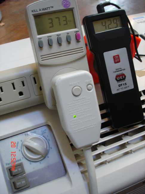 AC_fan+compressor If this is the case, you obviously have a proven winner. CASE #2 - Watt meter reads reads between 300 and 1500 watts, the unit is not cooling very well. The rear coils feel warm-to-hot. The front coils feel cold. Possible causes: a) Blocked Air Flow - This is very common. The filter in the front or the coils in the front or back of the unit are blocked. This may be why the unit was tossed. If you feel the coils in the front they should feel cold, also if you feel the coils in the back, they should feel warm. If the coils or air-filter are clogged it's simple to fix with a really strong vacuum cleaner, but for our heat pump purposes, you might not use the refrigerant-to-air coils at all. Liquid-to-liquid heat exchangers are much more efficient and open up a very interesting world of experimental possibilities. In the coming posts, I will show you how to buy or make liquid-to-liquid heat exchangers. b) The refrigerant has leaked. This is actually pretty unusual. If your unit is drawing more than 300 watts, and no cooling is happening, don't consider this unit at all. If refrigerant can get out, water can get in. Water in any amount, in the refrigerant system is bad for heat pumps. CASE #3 - Watt meter reads 30 to 80 watts during the whole test. This means your compressor never came on. Possible problems: a) The compressor is dead. Compressors are well-built, hermetically sealed and tested before they ever leave the factory. This would be very unlikely to be the case. b) The compressor starting capacitor is dead. The compressor starting cap is pretty darn reliable. This is also an unlikely case. c) The compressor thermal safety switch has failed. These are reliable, not so likely to fail. d) The switch on the front of the unit, or it's attached thermal sensor is bad. These can be the problem more likely than the above problems. But if these are the problem, it makes subsequent testing difficult. e) The temperature where the AC unit is being tested is too low for the cooling cycle to start. This is can be very likely. Most of the units I have looked at need to be warmer than about 65-70 degrees F to begin to work, even at Maximum cool. You may have a winner on your hands...maybe. So, if you can't verify that the compressor is actually working, it's really a crap-shoot. If you can get the unit for free or really, really cheap ($5), it might be worth it, but no matter how cheap, remember if it doesn't work, you still have to dispose of the carcass. Probably better to keep looking... Other things to consider: Look for the refrigeration identification tag. It will tell you some things like: 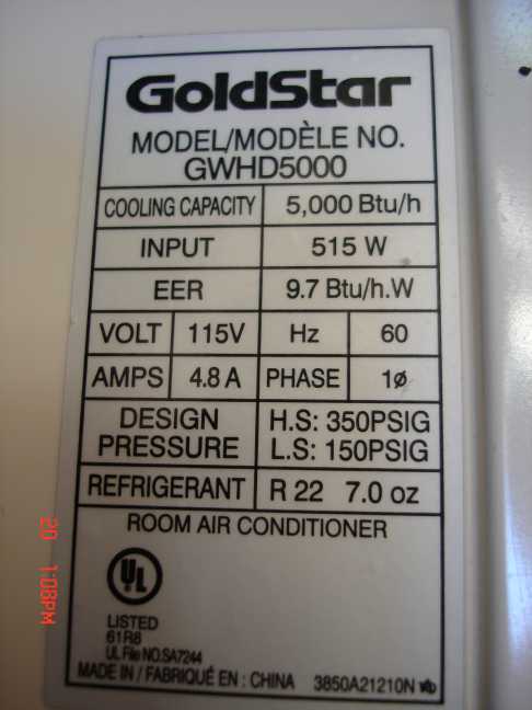 AC_the-tag * Cooling capacity - This is a sales figure. It may be accurate, or it may be exaggerated. This was what was found under 'lab conditions', wherever or whatever that is. * Input - This is about the maximum that the compressor and the fan will draw. * Refrigerant Pressures - Write this down, you may need this info later. * Refrigerant Type - This is the refrigerant that the unit was designed to use. Freon - Usually R-22 & R-12. They worked great except that they destroy the ozone layer and cause global warming. A real problem. These are very expensive to obtain and in some cases illegal if you don't have a HVAC license certificate. It is interesting to note that German Children seem prefer using Propane (AKA: R-290, Barbecue Gas, etc) because it is not damaging to the ozone layer and has zero global warming potential, and is incredibly cheap, and requires no license to obtain. It also works well with compressors designed for R-12 & R-22, as it uses the same type of lubricant (mineral oil type). It also seems to be similar enough to R-22 that it can be use without significant modification to the metering devices (more on that later). If I understand correctly, R-290 is being used as an automotive refrigerant in Australia. It is very flammable and produces water vapor and carbon dioxide (CO2) in the process. R-134a - Currently in use. Can be obtained in auto parts store. It does not destroy the ozone layer but does cause global warming. It will be restricted and then phased out. Compressors that use R134a will not be compatible with Freons, as the compressor oil is of a different base and does not play well with mineral oil compressor lubricants or the refrigerants that use these lubricants (R-22 or R-12 and R-290). I have heard of people having success by completely replacing the lubricant with mineral oil compressor lubricant. I have not tried this. Use of this refrigerant is reported to cause cancer of the testicles in lab rats. Under certain conditions, R-134a can burn and produces deadly gasses in the process. Regarding the size of the compressor, there's a saying that a cowboy can't have too much money, too fast a horse, or too many women. Well, what works for cowboys doesn't really work for heat pumps. if you have a large compressor, you pay more for it with every revolution. The trick is to figure the maximum BTUs or watts you will need, and design a little bit smaller. Plan to use a supplimental energy source to fill in during extreme conditions. So I have found smaller units to be the most interesting. I have a couple of bigger compressors (about 12,000 BTU) in the cellar for future experiments, but it's the smaller ones that really fascinate me now (small house heating, water pre-heating, high efficiency refrigeration, domestic water heat recovery, etc.) The AC unit that is in these pictures works perfectly, looks brand new, is the right size and had the fabric filter clogged with cat hair. It cost $25. So best of luck to you finding a good unit. Let me know what you found and how much it cost... Remember, don't open the refrigerant system until you're all prepared and ready to braze it back up. We have a way to go yet. (NEXT POST: We look under the hood to see what's going on...) Last edited by AC_Hacker; 05-27-09 at 09:19 PM.. Reason: add in-line images... |
|
|
|
| The Following 3 Users Say Thank You to AC_Hacker For This Useful Post: |
 |
| Tags |
| air conditioner, diy, gshp, heat pump, homemade |
|
|


 Hybrid Mode
